Building a Backpack Case for the Framework 16
Framework has been taking their sweet time releasing any kind of standalone enclosure for the FW16, even after releasing new mainboards! I believe this is the first (publicly available) standalone case for the FW16.
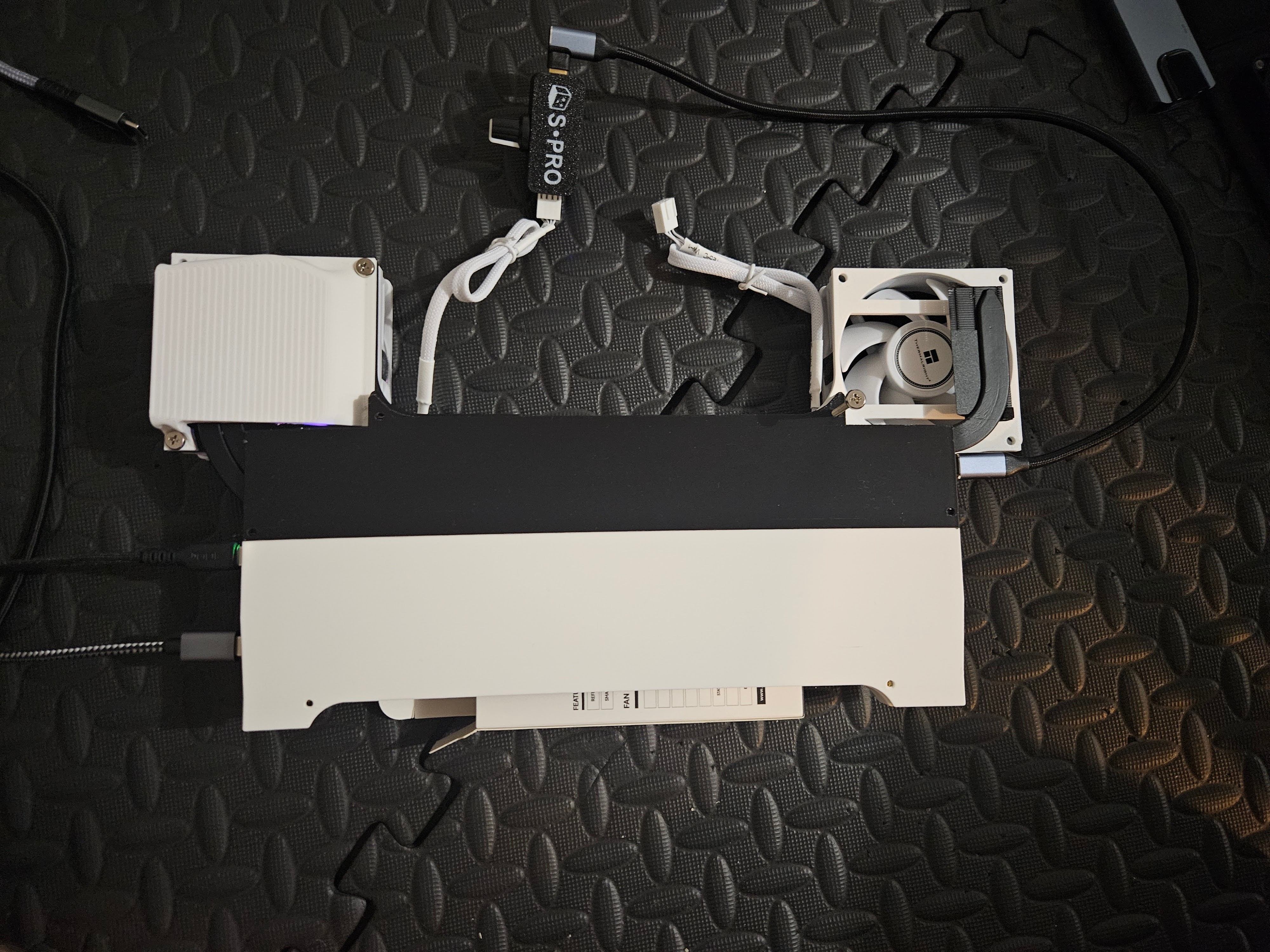
Overview & Files
The enclosure is derived from the Framework Backpack Repack (full credits go to Dregin_2599256). Only four STLs are needed: Motherboard Tray, Motherboard Cover, Fan Duct L, and Fan Duct R.
Bill of Materials
- Framework 16 mainboard
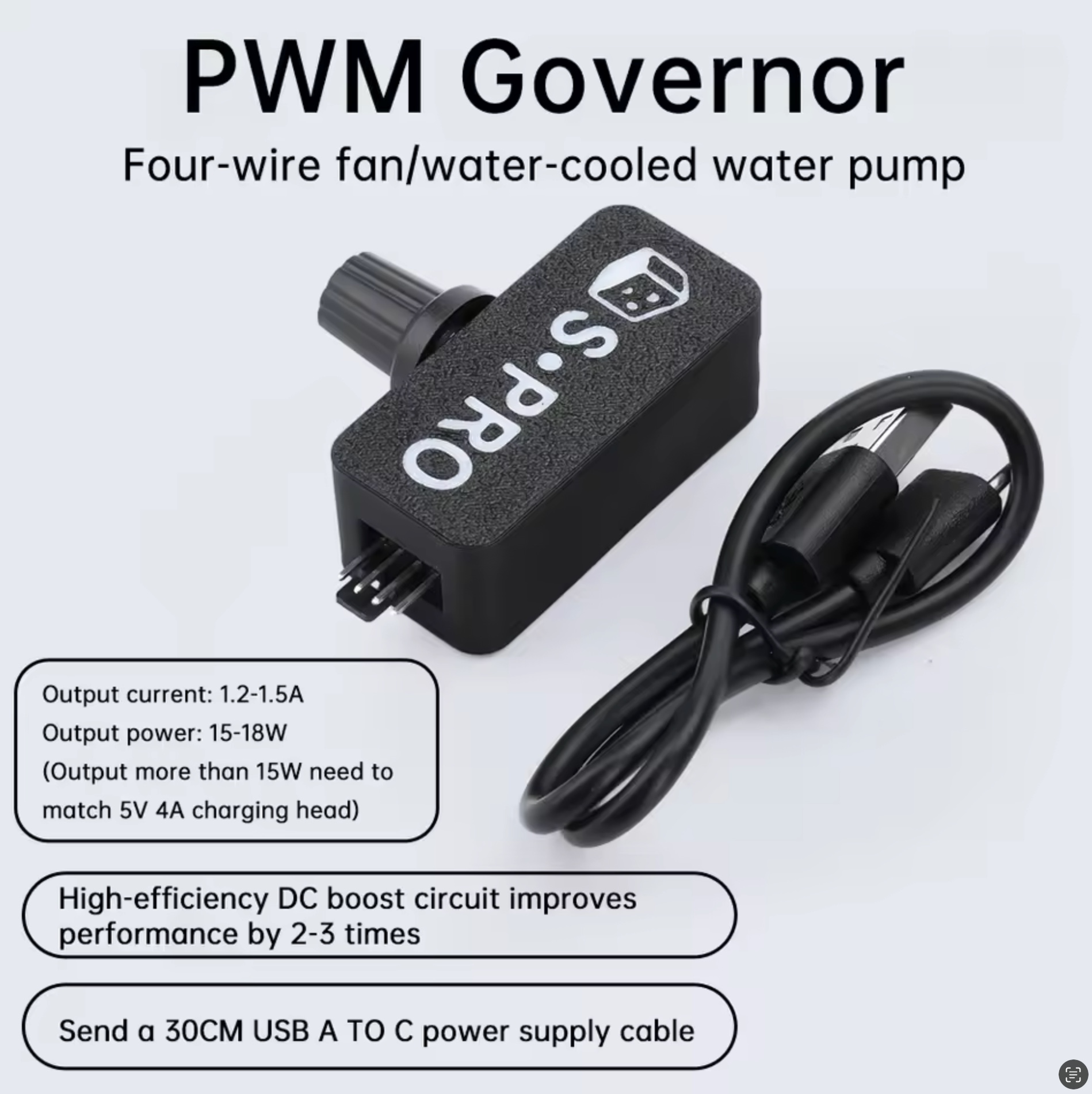
- DC boost converter with PWM dial (USB-C 5 V input → 12 V output)
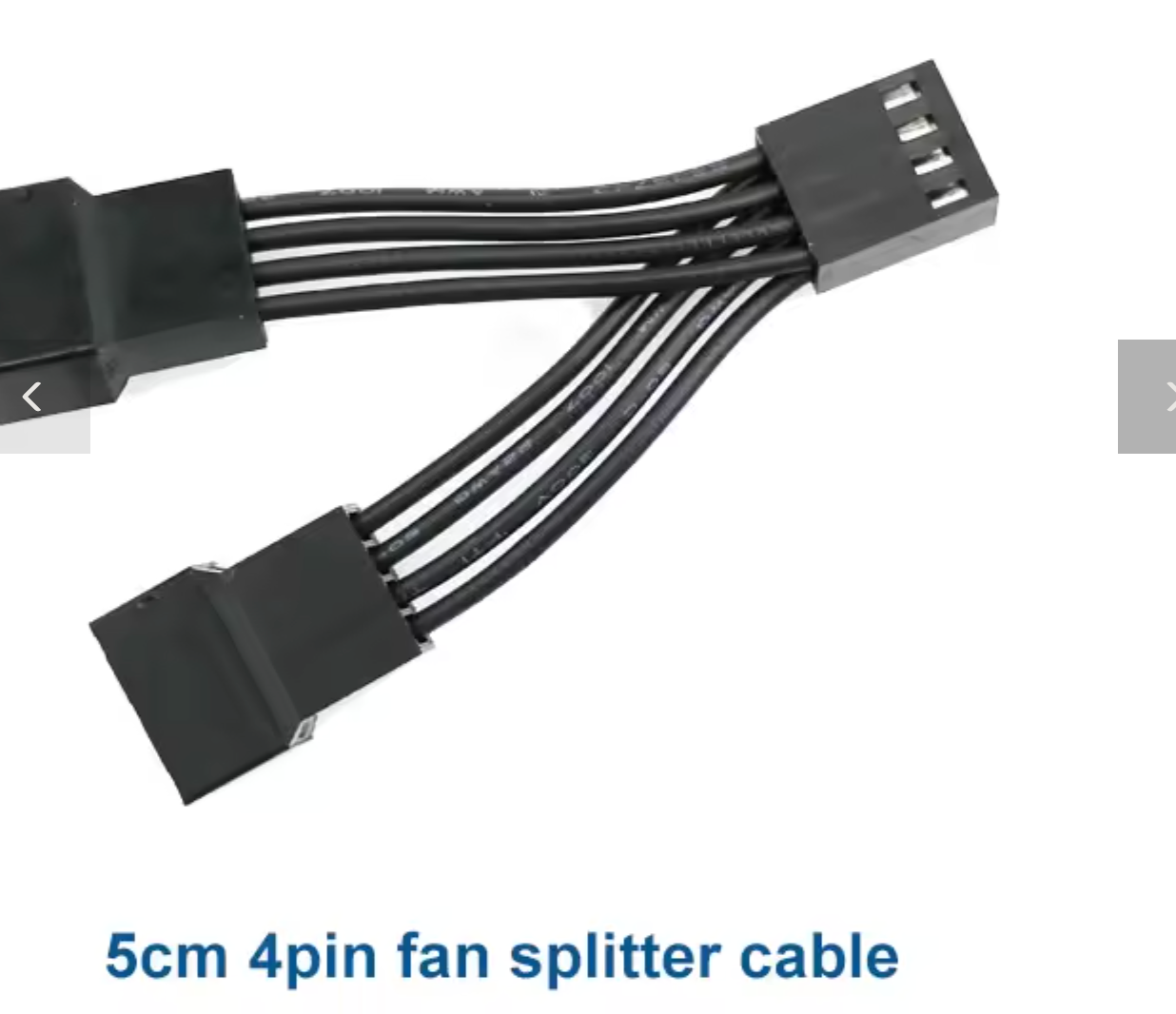
- 4-way PWM fan splitter
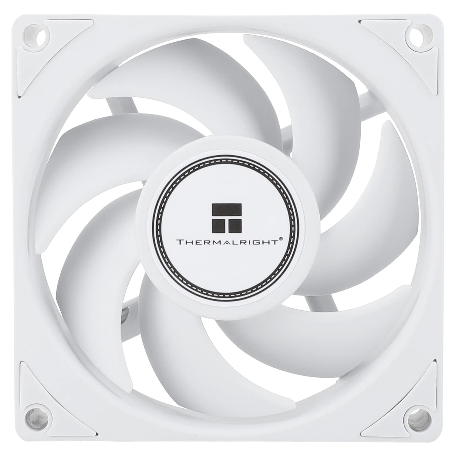
- Two 80 mm PWM fans (Thermalright TL-B8W shown) - one fan may be sufficient
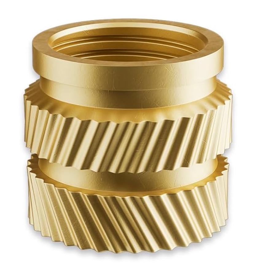
- M3 heat-set threaded inserts and assorted M3 screws
- USB-C to USB-C cable rated for ≥3 A
- Soldering iron
1. Configure BIOS for Standalone Mode
- Temporarily reconnect the stock display and keyboard modules.
- Enter BIOS > Boot Configuration.
- Enable Standalone Operation.
- Disable Standalone Detection.
- Set Require Power Button to Force Off.
- (Optional) Disable Quiet Boot so POST messages confirm a successful start.
- Shut down, disconnect the modules, and verify the board boots solely from USB-C power.
2. Print and Prepare the Enclosure
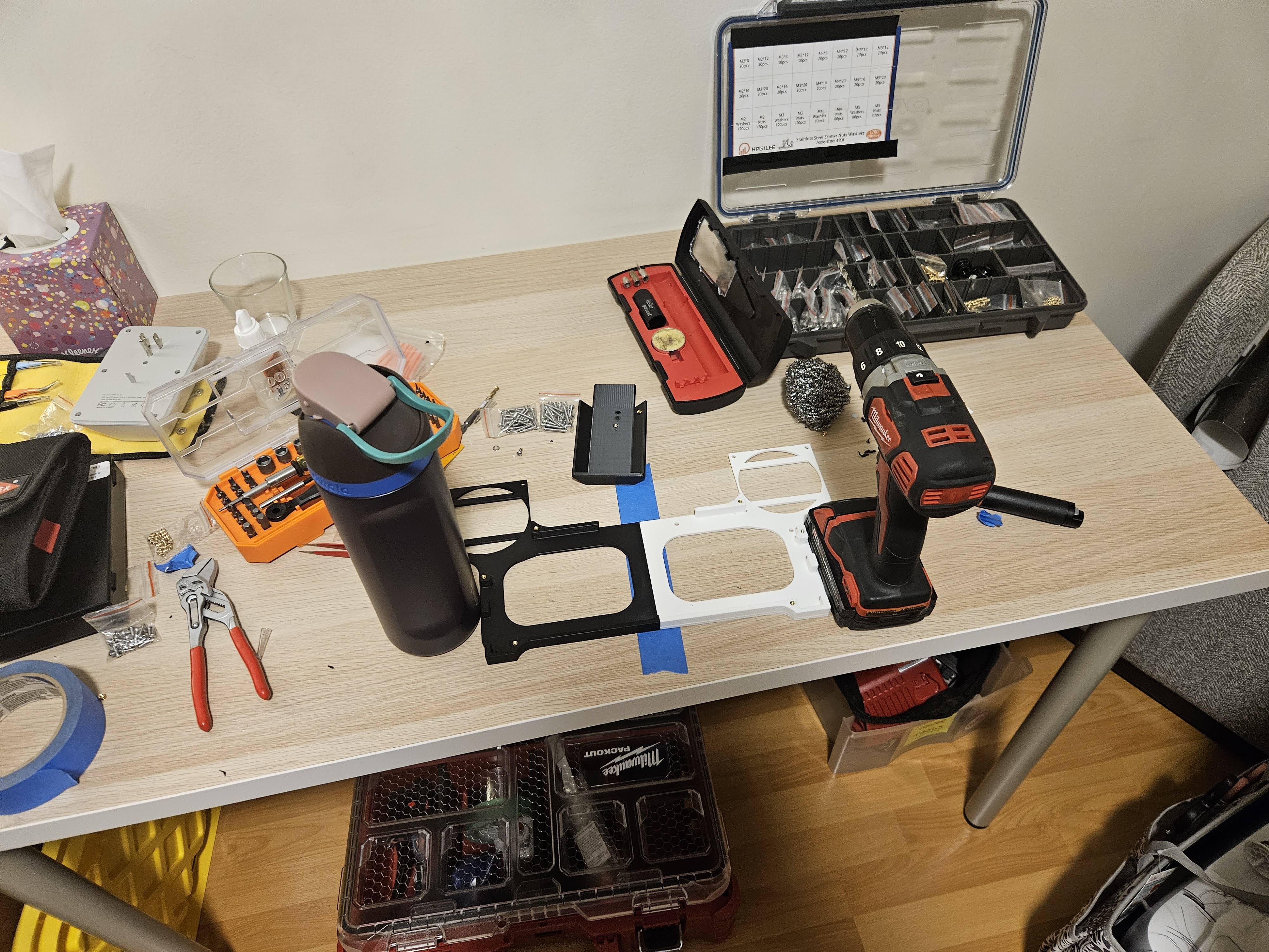
- Print the four required STLs. If the tray exceeds your build volume, split it and attach however you can (I used glue).
- Deburr screw holes and dry-fit each part. Ensure ducts align with the fan screw pattern.
- Install M3 heat-set inserts while parts lie flat. Heat the insert with a soldering iron (~220 °C) and press until flush.
3. Mount the Mainboard
- Position the mainboard on the tray.
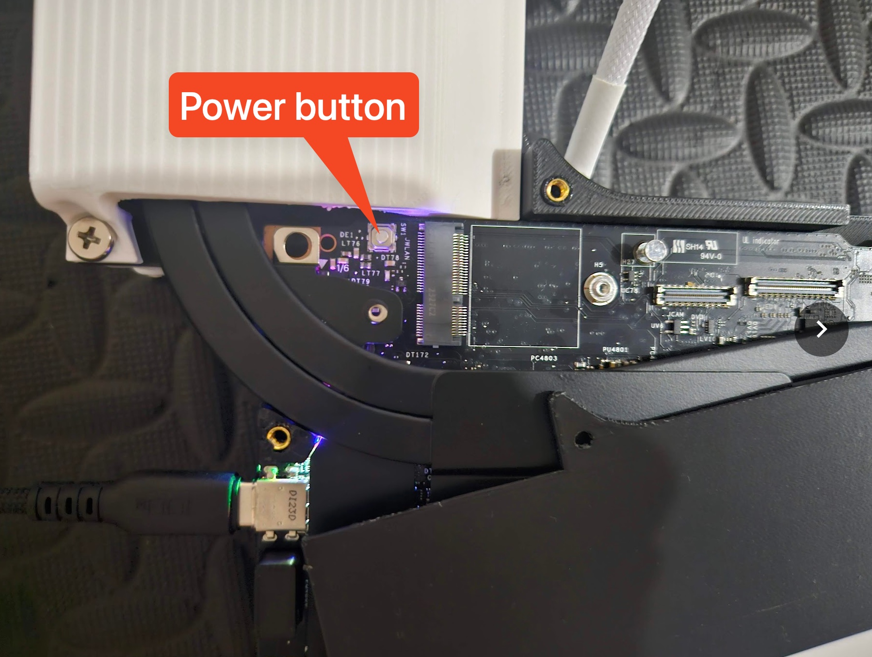
- Secure it with short M3 screws into the inserts. (note: there is no easy access to the power button once the top cover is screwed in)
4. Assemble and Wire Cooling
- Attach each 80 mm fan to its duct using the included fan screws.
- Fasten both ducts to the tray.
- Connect the fans to a PWM splitter, then feed the splitter from the boost converter’s 12 V output.
- Power the converter with a USB-C to USB-C cable plugged into the mainboard.
- Set the PWM knob around 50% to start; you can dial it down after thermal testing.
5. Functional Checks
- Power on the system and confirm both fans spin immediately.
- Run a CPU stress test; expect package temperatures in the mid-60 °C range at half speed with TL-B8W fans.
- Verify the board shuts down cleanly when USB-C power is removed.
- If auto power-on from AC fails, leave the cover’s upper-left screw loose or cut a finger-width notch for the power button. (for some reason auto power-on from AC doesn't work for me)
All modifications are reversible—reinstall the board in the Framework chassis at any time without replacing components.